|
Aggiornato il: 05-Dec-2010
|
|
|
|
|
The fast light Parallel Port Production PIC Programming
Software
|
|
|
|
|
DESCRIPTION
-
I've made this program because I needed an easy to use, easy to
configure and easy to extend full featured PIC (and most of the
serially programmed device) programming software.
Easy to extend beacuse it's based on:
the Mark Aiken's Odyssey - PIC Programming software, a well
written, documented and structured C++ program/library, used
as programming engine.
Really flP5 uses an enhanched version of Odyssey, I've added
the support for the 3 voltages 'production' programmers
and made some little changes to the library to best fit
with the GUI toolkit.
This library implementes the parallel port access and the
devices programming algorithms. It's almost the 90% of the
whole flP5 program.
the FLTK 1.1.3 or later - The Fast Light Tool Kit, it's a
multiplatform (*nix, MacOS, OS/2, Windows) C++ GUI toolkit,
it comes with its own interface designer, a lot of examples,
a very good documentation and it's very very easy to use.
Easy to configure because all the settings are easily accessible
and full documented by the extensive use of tooltips.
Easy to use tanks to the user friendly interface, the use of
few self explaining icons and the extensive use of tooltips.
FEATURES
Can support all the parallel port programmers supported by
Odyssey, plus the 3 voltages production
PIC programmers (on parallel port), as specified by Microchips.
New programmers can be easily configured on the fly.
Can support all the PIC devices supported by
Odyssey, here's a summary:
Tested:
PIC16F84,
| PIC12F629,
| PIC12F675,
| PIC16C76,
| PIC16C765,
| PIC16C84,
|
PIC16F74,
| PIC16F84,
| PIC16F877,
| PIC16F883,
| PIC16LF628,
| PIC18F252,
|
PIC18F452
|
Untested but should work:
PIC16C61,
|
PIC16C62,
|
PIC16C62A,
|
PIC16C62B,
|
PIC16C63,
|
PIC16C63A,
|
PIC16C64,
|
PIC16C64A,
|
PIC16C65,
|
PIC16C65A,
|
PIC16C65B,
|
PIC16C66,
|
PIC16C67,
|
PIC16C71,
|
PIC16C72,
|
PIC16C72A,
|
PIC16C73,
|
PIC16C73A,
|
PIC16C73B,
|
PIC16C74,
|
PIC16C74A,
|
PIC16C74B,
|
PIC16C76,
|
PIC16C77,
|
PIC16C84,
|
PIC16C620,
|
PIC16C620A,
|
PIC16C621,
|
PIC16C621A,
|
PIC16C622,
|
PIC16C622A,
|
PIC16C710,
|
PIC16C711,
|
PIC16C712,
|
PIC16C716,
|
PIC16C745,
|
PIC16C765,
|
PIC16C773,
|
PIC16C774,
|
PIC16C923,
|
PIC16C924,
|
PIC16F73,
|
PIC16F74,
|
PIC16F76,
|
PIC16F77,
|
PIC16F83,
|
PIC16F84A,
|
PIC16F627,
|
PIC16LF627,
|
PIC16F628,
|
PIC16LF628,
|
PIC16F870,
|
PIC16F871,
|
PIC16F872,
|
PIC16F873,
|
PIC16F874,
|
PIC16F876,
|
PIC16F877,
|
PIC18F248,
|
PIC18F252,
|
PIC18F252,
|
PIC18F258,
|
PIC18F442,
|
PIC18F448,
|
PIC18F452,
|
PIC18F458,
|
PIC18F2221,
|
PIC18F4221,
|
PIC18F2321,
|
PIC18F4321,
|
PIC18F2410,
|
PIC18F4410,
|
PIC18F2430,
|
PIC18F4420,
|
PIC18F2450,
|
PIC18F4450,
|
PIC18F2455,
|
PIC18F4455,
|
PIC18F2480,
|
PIC18F4480,
|
PIC18F2510,
|
PIC18F4510,
|
PIC18F2515,
|
PIC18F4515,
|
PIC18F2520,
|
PIC18F4520,
|
PIC18F2525,
|
PIC18F4525,
|
PIC18F2550,
|
PIC18F4550,
|
PIC18F2580,
|
PIC18F4580,
|
PIC18F2585,
|
PIC18F4585,
|
PIC18F2610,
|
PIC18F4610,
|
PIC18F2620,
|
PIC18F4620,
|
PIC18F2680,
|
PIC18F4680,
|
PIC16F882,
|
PIC16F884,
|
PIC16F886,
|
PIC16F887
|
New PIC devices can be easily added on the fly, but, in
the current verion of the software, they must folow the
Microchip's specifications listed below:
DS30034D - PIC16F62X
DS30228J - PIC16C6XX/7XX/9XX
DS30262C - PIC16F8X
DS30324B - PIC16F7X
DS39025F - PIC16F87X
DS41173B - PIC12F6XX
DS39592D - PIC18F1220, 1320, 2220, 2320, 4220, 4320
As Mark Aikens says, thank to his Odyssey - PIC
programming software:
“This program has the potential to program
any serially programmed device and I would like to be
able to program any PIC in existence (under Linux of
course).” ...
... and now, even under Windows.
USAGE
-
The interface is subdivided into two areas: the Operative
area on the left and the Configuration area,
on the right.
From the Operative area you can:
|

|
chose the device to work on.
|
|

|
load an hex file into the memory buffer to write into or
compare to the device memory.
|
|

|
write the content of the memory buffer into an hex file.
|
|
Device oriented buttons
|

|
load the content of the device memory into the memory buffer.
|
|

|
erase the content of the device memory.
|
|
|
erase the content of the device memory.
|
|

|
perform a blank check of the device memory.
|
|

|
load the content of the memory buffer into the device memory.
|
|

|
verify the content of the device memory compared to the
memory buffer.
|
|

|
switch on/off the Vdd line to enter in the On Circuit
Test Mode.
In this mode the programmer can be used as power source
for the circuit in development.
|
|

|
put the Vpp line to GND to reset the micro controller.
This control simulates the hardware reset.
|
|
|
view the content of the memory buffer either in hexadecimal
format or in disassembled format, depending on the
chosen device.
|
When you choose one of the device oriented buttons
for the first time or after changed the device or the
programmer, the programmer calibration procedure
will be automatically executed.
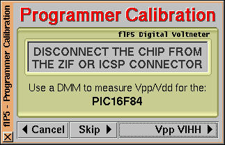
The Programmer Calibration Procedure consists
on a wizard showing the optimal values for the Vpp and Vdd
voltages, if your programmer allows you to trim the Vpp and
Vdd values then you need a DMM to attach to the ICSP Vpp and
ICSP Vdd connections.
Start of the calibration procedure, clicking on
Cancel will terminate the selected operation,
while Skip, when active, allows you to
skip the calibration procedure ...
|
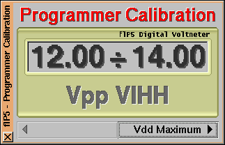
... measure the Vpp VIHH value, it must be in
the range shown. If you aren't using a production programer
the next step will be Vdd programming ...
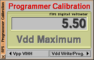
|
... measure the Vdd maximum value, it must
match the value shown ...
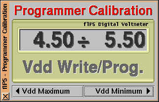
|
... measure the Vdd programming value, it must
be in the shown range. If you aren't using a production
programer this is the last measure you have to do ...
|
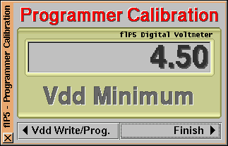
... measure the Vdd minimum value, it must
match the shown value ...
|
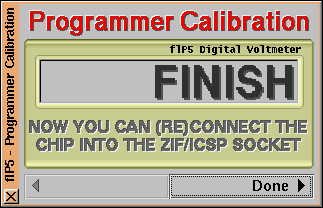
... you are done, now can start the selected operation.
|
From the Configuration area you can:
|

|
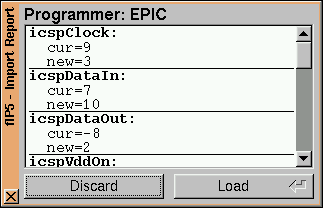
load the devices/programmers configuration from a file. The
changes between the current and the new configuration,
for each device or programmer loaded, will be shown by
the following panel:
|
|

|
create a new device/programmer configuration entry.
|
|

|
edit the configuration for the chosen device/programmer.
|
|

|
duplicate the configuration of the chosen device/programmer.
|
|

|
store the configuration changes into the program memory.
|
|

|
revert the configuration changes or delete the
device/programmer configuration from the program memory.
|
The Configuration area is furthermore subdivided
into Device Config. and Programmer
Config. tabs.
|
|
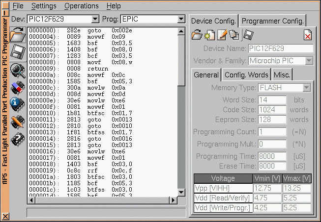
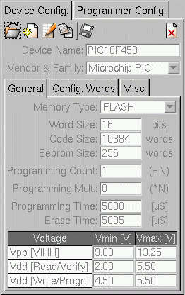
Device Config. tab - General settings
|
|
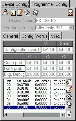
Device Config. tab - Config. Words
settings
Here you can:
add

modify
duplicate
store
and remove
the device configuration words which are listed in the list
placed on the left of the Config. Words toolbar,
here you can select the word to edit and change the bitmask
of the various fields from the above texts.
|
|
|
|
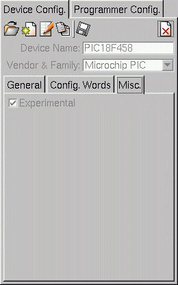
Device Config. tab - Misc. settings
Devices marked as Experimental have never
been programmed with this software by anyone. When you
succesfully program a device with this software you can
toggle off the Experimental mark.
In the list of devices the experimental ones are
written in blue,
otherwise are written in black.
|
|
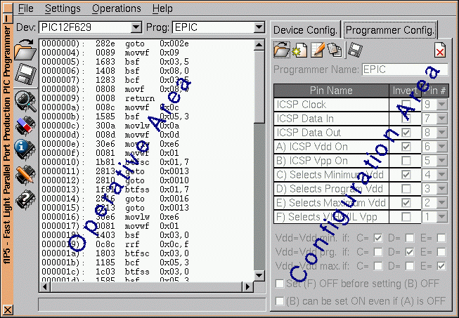
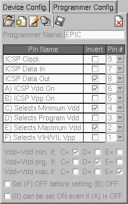
Programmer Config. tab.
Here you can:
edit the programmer name.
configure the pin for the connection of the programmer
to the parallel port. If more than one connections have
the same Pin #, those connections are
marked with a yellow background.
specify the signals configuration to obtain the
Vdd min/max/programming values for the 3 voltages
production programming.
specify the signals configuration to put Vpp to GND.
specify wether Vdd can be switched OFF before switching
OFF Vpp.
|
|
From the main menu you can also set the parallel port the
programmer is connected to and, under Linux, if possible,
the access method to the parallel port, either direct or via
a user mode device.
TODO
- Make more tests
- Add support for other vendor/family devices (AVR, Scenix, ...)
- Use MinGW/DevC++ instead of Visual C/C++
to build the Windows executable
- Correct all the bugs
REQUIREMENTS (to install flP5 from the sources)
-
For all the platforms:
-
FLTK 1.1.7 or later
CMake
For Windows only:
-
Visaul C/C++ 6.0
Tarma Installer 2.45
DOWNLOAD
-
The sources for Linux and Windows:
-
 ChangeLog
flP5-1.1.10-src.tar.gz
flP5-1.1.8-src.tar.gz (old release)
-
The user manual:
-
flP5-1.0.0-doc.tar.gz
This package contains the user manual in PDF and
StarWriter / OpenOffice.org 1.0.2 Writer SXW
format.
Extract this package in the share area where you
installed flP5.
- For Linux (i.e. if flP5 was installed in
/usr/local):
         cd /usr/local/share

         tar -xvzf flP5-X.Y.Z-doc.tar.gz
- For Windows (i.e. if flP5 was installed in
C:\Programs\flP5):
         Extract flP5-X.Y.Z-doc.tar.gz into
         C:\Programs\flP5\share with WinZip
The content of the user manual is the same of this page
plus the schematic and PCB/components layouts to build
the P5 programming hardware.
flP5-1.1.9-Windows.zip (07-Jun-2010) the Windows installer
flP5-1.1.8-Windows.zip (15-Jun-2008) the Windows installer (old release)
ACKNOWLEDGEMENTS
-
Slovak translation by Pavol Lajciak.
(paulusmaria AT users DOT sourceforge DOT net)
DS39592D: Edward A. Hildum
(ehildum AT comcast DOT net)
|
|
|
|
|
|
|